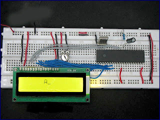
 Here we use a 16x2 LCD which is interfaced by P89V51RD2 which is a 8051 micricontroller.
A 16x2 LCD is shown below.
Pin configuration is written behind this LCD as...
1 - GND
2 - VCC (+5V)
3 - VEE (FOR CONTRAST)
4 - RS (REGISTER SELECT)
5 - RW (READ/WRITE)
6 - EN (ENABLE)
7-14 - DATA PINS D0-D7
15 - LED PLUS
16 - LED MINUS
Components required :-
- 10uf electrolytic capacitor
- 10k ohm registance
- 10k ohm variable registance
- 11.059 MHZ crystal oscilltor
- 16x2 LCD
- P89V51RD2 IC
- 5v battery
Circuit diagram : -
Burn this code in microcontroller and Make the connections..
Code :-
----------------------------------------------------------------------------------------------------------------------------------
#include <REG51.H>
int i,j,k;
sbit RS=P3^0;
sbit RW=P3^1;
sbit EN=P3^6;
void delay();
void lcd_cmd(unsigned char value);
void lcd_data(unsigned char value);
char a[6]="ashish";
char b[8]="chittora";
void main()
{
while(1)
{
lcd_cmd(0x38);
delay();
lcd_cmd(0x0e);
delay();
lcd_cmd(0x06);
delay();
lcd_cmd(0x01);
delay();
for(j=0;j<6;j++)
{
lcd_data(a[j]);
delay();
}
lcd_cmd(0xc0);
for(k=0;k<8;k++)
{
lcd_data(b[k]);
delay();
}
}
}
void delay()
{
for(i=0;i<2;i++)
{
TMOD=0X01;
TH0=0X4B;
TL0=0XFD;
TR0=1;
while(TF0==0);
TF0=0;
TR0=0;
}
}
void lcd_cmd(unsigned char value)
{
RS=0;
RW=0;
P2=value;
EN=1;
delay();
EN=0;
}
void lcd_data(unsigned char value)
{
RS=1;
RW=0;
P2=value;
EN=1;
delay();
EN=0;
}
----------------------------------------------------------------------------------------------------------------------------------
after this switch on the circuit.
Note :- If you have problem to see characters in LCD then reduce the contrast level of LCD by increasing the resistance of 10k variable resistor.
Contact us for the code in c language.
IF YOU HAVE ANY QUERY THAN CONTACT US OR GIVE YOUR QUERY IN THE QUERY OPTION.
GOOD LUCK


