
Introduction :
We can give the instruction to the microcontroller using computer with "HYPER TERMINAL" software. This software gives and receive the instructions means characters or strings in form of serial data. Now this data can be processed with a microcontroller and can be send using RF module to the receiver robot.

RS232 Cable :-
We use USB to SERIAL RS232 cable for sending the data to the microcontroller from computer. (for communication drivers of rs232 cable must be installed on your computer).
DB9 serial port :-
We mount female port on the transmitter because cable contains male port.
.jpg)
.jpg)
MAX232 IC (Voltage Shifter) :-
MAX232 IC is used to shift the voltage level of computer's input to level of microcontroller. Means input from serial cable first given to the MAX232 and then given to the controller.
Connection of serial port with MAX232 is shown in figure.


8051 :-

Encoder :-
We use HT12E IC for encoding the signal. This is a 4 bit encoder which encodes the 4 bits into a singal bit and transmit it via RF transmitter.
 A0-A7 :-
pin no. 1 - 8 is the address line which is used for the safety purpose. You can leave blank these pins. These pins are initially high (5v) for using them lets have a example :-
Let If you ground the pins 1,2,3,4 in encoder then its address becomes 11110000 so this encoder transmit the signal to the address 11110000 so for decoding this signal decoder address must have the same address as in encoder that is 11110000. so you have ground the pin 1,2,3,4 at decoder.
AD0-AD3 :-
These are the address and data lines but we use them only for data. These are 4 input pins for 4 bit binary data for encoding.
TE :-
Transmit Enable. These should be always low(grounded) for transmission of data.
OSC1-OSC2 :-
We connect resistance of 1.1M OHM for proper oscillation.
Output :-
This is the pin for encoded data output which is further connected to the RF transmitter data pin.
DECODER :-
We use HT12D IC for decoding the signal. This is a 4 bit decoder which decodes the singal bit into 4 bits and it receive the single bit via RF receiver.

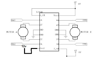 L293D(Motor Driver) :-
This IC is used to drive the motors
according to the signal from microcontroller.
Circuit Diagram For Transmitter :-

Components Required :-
7805 IC - 2
12v battery - 2
1N4007 diode - 2
1000uf capacitior - 2
LED - 4
330 ohm resistance - 4
10uf capacitor - 3
0.1 uf capacitor - 4
33pf capacitor - 4
11.0592 crystal oscillator - 2
P89V51RD2 controller - 2
max232 IC - 1
female serial port - 1
RS232 usb to serial cable - 1
push button - 2
10k ohm resistance - 2
HT12E IC - 1
HT12D IC - 1
1.1M ohm resistance - 1
51k ohm resistance - 1
RF transreciever module - 1
L2393D ic - 1
DC motors of 100 rpm - 2
caster wheel - 1
chasis - 1
connecting wires
PCB


Code (for transmitter) :-
----------------------------------------------------------------------------------------------------------------------------------
//Program to interface computer with 8051 microcontroller (8051 architecture)
#include<reg51.h> //header file
unsigned char rcv_data; //variable for data recieving
void receive() //Function to recieve data serialy wfrom RS232
{
while(RI==0); //untill RI is high it will check the condition of RI
rcv_data = SBUF; // it will recieve the character in sbuf regifter of 8051......when wholw data is being recieved RI becomes high.
RI=0; // reset the RI
}
void compare()
{
if(rcv_data=='w') //forward
P2=0x01;
else if(rcv_data=='a') // left
P2=0x02;
else if(rcv_data=='s') // right
P2=0x03;
else if(rcv_data=='d') // backward
P2=0x04;
else
P2=0x00;
}
void main()
{
P2=0x00; //intialize P2 as output port
TMOD=0x20; //Enable Timer 1 in mode 2
TH1=0XFD; // it used to give delay of 1 second to timer 1
SCON=0x50; // initaiize uart cable mode for reciving data from serial cable
TR1=1; // start timer 1
while(1) // infinite loop
{
receive(); // call recieve function
compare(); // call compare function
}
}
Code (for receiver) :-
----------------------------------------------------------------------------------------------------------------------------------
#include<reg51.h>
void main()
{
P1=0x0f; //initialize P1 as input port
P2=0x00; // initialize P2 port as output port
while(1)
{
if(P1==0x08)
{
P2=0x09;
}
else if(P1==0x04)
{
P2=0x01;
}
else if(P1==0x0c)
{
P2=0x06;
}
else if(P1==0x02)
{
P2=0x08;
}
else
{
P2=0x00;
}
}
}
----------------------------------------------------------------------------------------------------------------------------------
We can give the instruction to the microcontroller using computer with "HYPER TERMINAL" software. This software gives and receive the instructions means characters or strings in form of serial data. Now this data can be processed with a microcontroller and can be send using RF module to the receiver robot.
RS232 Cable :-
We use USB to SERIAL RS232 cable for sending the data to the microcontroller from computer. (for communication drivers of rs232 cable must be installed on your computer).
DB9 serial port :-
We mount female port on the transmitter because cable contains male port.
MAX232 IC (Voltage Shifter) :-
MAX232 IC is used to shift the voltage level of computer's input to level of microcontroller. Means input from serial cable first given to the MAX232 and then given to the controller.
Connection of serial port with MAX232 is shown in figure.

8051 :-
Encoder :-
We use HT12E IC for encoding the signal. This is a 4 bit encoder which encodes the 4 bits into a singal bit and transmit it via RF transmitter.
pin no. 1 - 8 is the address line which is used for the safety purpose. You can leave blank these pins. These pins are initially high (5v) for using them lets have a example :-
Let If you ground the pins 1,2,3,4 in encoder then its address becomes 11110000 so this encoder transmit the signal to the address 11110000 so for decoding this signal decoder address must have the same address as in encoder that is 11110000. so you have ground the pin 1,2,3,4 at decoder.
AD0-AD3 :-
These are the address and data lines but we use them only for data. These are 4 input pins for 4 bit binary data for encoding.
TE :-
Transmit Enable. These should be always low(grounded) for transmission of data.
OSC1-OSC2 :-
We connect resistance of 1.1M OHM for proper oscillation.
Output :-
This is the pin for encoded data output which is further connected to the RF transmitter data pin.
DECODER :-
We use HT12D IC for decoding the signal. This is a 4 bit decoder which decodes the singal bit into 4 bits and it receive the single bit via RF receiver.

- Address line A0-A7 must have the same configuration as in encoder. Otherwise it will not work.
- D0-D3 are data output.
- Input pin is the single bit input from RF receiver.
- We connect resistance of 51K ohm to osc1 and osc2 for proper oscillation.
- VT pin is the indicator that data is received for receiver. so we connect here a Led with 330 ohm resistance.
RF module (radio frequency) :-


For making the robot wireless we use a RF module which consist a transmitter or a receiver. RF module transmits encoded signal so we have to use a Encoder - Decoder pair for encoding the signal at transmitter and decoding the signal at receiver.
RF module works on 434MHz frequency.
 L293D(Motor Driver) :-
This IC is used to drive the motors
according to the signal from microcontroller.
We use L293d or other motor driver
IC's for driving the motors because DC
IC's for driving the motors because DC
motors gives Back EMF in rotation.
So from preventing the circuit from
this back emf we use motor drivers.
| original image of DB9 connector is shown above |
Receiver Circuit Diagram :-

7805 IC - 2
12v battery - 2
1N4007 diode - 2
1000uf capacitior - 2
LED - 4
330 ohm resistance - 4
10uf capacitor - 3
0.1 uf capacitor - 4
33pf capacitor - 4
11.0592 crystal oscillator - 2
P89V51RD2 controller - 2
max232 IC - 1
female serial port - 1
RS232 usb to serial cable - 1
push button - 2
10k ohm resistance - 2
HT12E IC - 1
HT12D IC - 1
1.1M ohm resistance - 1
51k ohm resistance - 1
RF transreciever module - 1
L2393D ic - 1
DC motors of 100 rpm - 2
caster wheel - 1
chasis - 1
connecting wires
PCB
Process to send data from computer to controller on transmitter :-
Follow the steps :-
- open hyper terminal. And write any connection name and click ok.
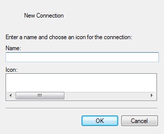
- Select your com port at where the rs232 cab is connected. To see your com port right click on my computer and go to >manage>device manager>ports.
- now a window open like this.

- click restore default and ok.

- click to connection propertoes.

- a window opens. go to settings.

- go to ASCII setup.

- check all the boxes. give 1000 millisecond delay and click ok.
- start pressing the buttons you specified in your program like w, a, s, d.
Code (for transmitter) :-
----------------------------------------------------------------------------------------------------------------------------------
//Program to interface computer with 8051 microcontroller (8051 architecture)
#include<reg51.h> //header file
unsigned char rcv_data; //variable for data recieving
void receive() //Function to recieve data serialy wfrom RS232
{
while(RI==0); //untill RI is high it will check the condition of RI
rcv_data = SBUF; // it will recieve the character in sbuf regifter of 8051......when wholw data is being recieved RI becomes high.
RI=0; // reset the RI
}
void compare()
{
if(rcv_data=='w') //forward
P2=0x01;
else if(rcv_data=='a') // left
P2=0x02;
else if(rcv_data=='s') // right
P2=0x03;
else if(rcv_data=='d') // backward
P2=0x04;
else
P2=0x00;
}
void main()
{
P2=0x00; //intialize P2 as output port
TMOD=0x20; //Enable Timer 1 in mode 2
TH1=0XFD; // it used to give delay of 1 second to timer 1
SCON=0x50; // initaiize uart cable mode for reciving data from serial cable
TR1=1; // start timer 1
while(1) // infinite loop
{
receive(); // call recieve function
compare(); // call compare function
}
}
----------------------------------------------------------------------------------------------------------------------------------
Code (for receiver) :-
----------------------------------------------------------------------------------------------------------------------------------
void main()
{
P1=0x0f; //initialize P1 as input port
P2=0x00; // initialize P2 port as output port
while(1)
{
if(P1==0x08)
{
P2=0x09;
}
else if(P1==0x04)
{
P2=0x01;
}
else if(P1==0x0c)
{
P2=0x06;
}
else if(P1==0x02)
{
P2=0x08;
}
else
{
P2=0x00;
}
}
}
----------------------------------------------------------------------------------------------------------------------------------
IF YOU HAVE ANY QUERY THAN CONTACT US OR GIVE YOUR QUERY IN THE QUERY OPTION.