Tuesday 14 May 2013

DIGITAL CLOCK WITH 8051

Here is a LCD based Digital Clock project using only 8051. This digital clock is configured in a 12 hour mode and switches are given for set the hours, minutes, and AM/PM.

Note :-
              Use push on - push off switches here do not use toggle switches for set the hours, minute, am/pm and start. For reset of microcontroller use toggle switch.
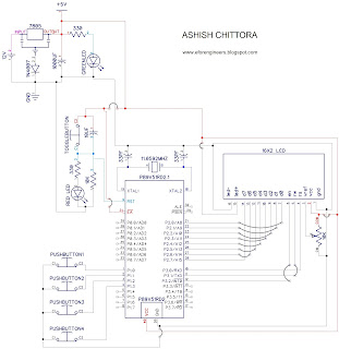
Circuit Diagram :-
                   

 download and zoom in the photo so you can clearly all the connections.

Pink lines - 12 volt
Red lines - 5 volts
Black lines - ground
Blue lines - data


Components Required :-

7805 IC - 1
1N4007 diode - 1
330 0HM RESISTANCE - 2
10K OHM RESISTANCE - 2
10K OHM VARIABLE RESISTANCE - 1
33PF CAPACITOR - 2
10UF CAPACITOR - 1
1000UF CAPACITOR - 1
11.0592 MHZ CRYSTAL OSCILLATOR - 1
GREEN LED - 1
RED LED - 116X2 LCD - 1
12 volt battery upto 1.5 amp. -1
P89V51RD2 MICROCONTROLLER - 1
TOGGLE BUTTON - 1
PUSH ON-OFF SWITCH - 1
16x2 LCD - 1
MALE AND FEMALE CONNECTORS LINES
CONNECTING WIRES.


Process to set Time :-

Start button - 1st button
hour set - 2nd button
minute set - 3rd button
am-pm set - 4th button


  • push the start button. (start button off and clock do not start)
  • now push the hour or minute buttons according to set time (do no push repeatedly push only one time).
  • Now Push off the hour and minute buttons for stopping the time increasing.
  • Push the am-pm button according to the am-pm
  • Now push on the start button now for starting the clock. 


Code :-

----------------------------------------------------------------------------------------------------------------------------------

// Program to make a digital clock using LCD

#include<reg51.h> 
#define m_sec 10
sbit rs = P3^0;
sbit rw = P3^1;
sbit en = P3^2;
sbit hrs=P1^1;
sbit mns=P1^2;
sbit start=P1^0;
sbit am_pm=P1^3;
int hr ,hr1=0;
int min,min1=0;
int sec,sec1=0,ampm=0;

void delay(unsigned int msec)   // Time delay funtion
{
int i,j ;
for(i=0;i<msec;i++)
  for(j=0;j<1275;j++);
}

                
void lcd_cmd(unsigned char item)   // Function to send command on LCD
{
P2 = item;
rs= 0;
rw=0;
en=1;
delay(1);
en=0;
return;
}

void lcd_data(unsigned char item)  // Function to send data on LCD
{
P2 = item;
rs= 1;
rw=0;
en=1;
delay(1);
en=0;
return;
}

void lcd_data_string(unsigned char *str)  // Function to send string on LCD
{
  int i=0;
  while(str[i]!='\0')
{
    lcd_data(str[i]);
    i++;
    delay(1);
}
return;
}

lcd_data_int(int time_val)   // Function to send number on LCD
{
int int_amt;
int_amt=time_val/10;
lcd_data(int_amt+48);
int_amt=time_val%10; 
lcd_data(int_amt+48);
}

void lcd(unsigned char str1[10])  // Function to initialize LCD
{
lcd_cmd(0x38);  //2 LINE, 5X7 MATRIX
lcd_cmd(0x0e);  //DISPLAY ON, CURSOR BLINKING
delay(m_sec);
lcd_data_string(str1);
}

void set_hr1()  // Function to set hour
{
hr1++;
if(hr1>11)
hr1=0;
lcd_cmd(0xc3);
lcd_data_int(hr1);
lcd_data(':');
}

void set_min1()  // Function to set minute
{
min1++;
if(min1>59)
min1=0;
lcd_cmd(0xc6);
lcd_data_int(min1);
}

void main()
{
int k;
start=1;
hrs=1;
mns=1;
lcd_cmd(0x01);
lcd_cmd(0x83);
lcd("SET TIMING");
lcd_cmd(0xc3);
lcd_data_int(hr1);
lcd_data(':');
lcd_data_int(min1);
while(start==0)
{
  delay(200);
  if(hrs==0)
  set_hr1();
  if(mns==0)
  set_min1(); 
}

if(am_pm==0)
{
  lcd_cmd(0xc8);
  lcd_data_string("am");
  ampm=0;
}

if(am_pm==1)
{
  lcd_cmd(0xc8);
  lcd_data_string("pm");
  ampm=1;
}
delay(200);
lcd_cmd(0x01);
while(1)
{
  for(k=0;k<2;k++)
  {
   for(hr=hr1;hr<12;hr++)
   {
    for(min=min1;min<60;min++)
     {
      for(sec=0;sec<60;sec++)
      {
       lcd_cmd(0x82);
       delay(1);
       lcd_data_int(hr);
       lcd_data(':');
       lcd_data_int(min);
       lcd_data(':');
       lcd_data_int(sec);
       if(ampm==0)
       {
        lcd("am");
       }
       else
       {
        lcd("pm");
       }
       lcd_data_string("    ");
       delay(100);
      }
     }
    min1=0;
    }
  if(ampm==0)
  ampm=1;
  else
  ampm=0;
  hr1=0;
  }
}
}


 ---------------------------------------------------------------------------------------------------------------------------------
Calculations in this program are standard.
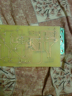
Pictures :-


Video :-


Proteus video :-


IF YOU HAVE ANY QUERY THAN CONTACT US OR GIVE YOUR QUERY IN THE QUERY OPTION.      
                                                            GOOD LUCK

More embedded projects >>....                                                More MAT LAB projects>>...


Sunday 12 May 2013

GESTURE CONTROLLED ROBOT(Hand Glove Based)

Description :-
                        As you all know that Gesture Technology becomes very popular in very short time period.

So we implement here a very small application of Gesture Technology A gesture control robot.

here we make circuit on a hand glove using LDR's and LED's on our four fingers. When we turn our fingers after wearing the glove the robot moves forward, backward, left and right. So ultimately you can control your robot on your fingers.

We used here LDR as a light sensor. When light of the LED falls on LDR the resistance LDR is very high and it does not give any output. Now when we turn our finger the light of LED do fall on LDR and resistance of LDR becomes very low and it gives output.

LDR gives the analog signal so we have to convert it in Digital signal. See here....                                    .ANALOG TO DIGITAL CONVERTERS

We uses LM324 IC for ADC.

LM324 ANALOG TO DIGITAL CONVERTER :-


we connects the gesture inputs to pin no. 2,6,9,13. And variable resistors at pin no. 3,5,10,12.


For this project we makes two Circuits a transmitter and a receiver. Transmitter is connected with the hand glove circuit and receiver is made on robot.


RF module (radio frequency) :-
                                                        For making the robot wireless we use a RF module which consist a transmitter or a receiver. RF module transmits encoded signal so we have to use a Encoder - Decoder pair for encoding the signal at transmitter and decoding the signal at receiver.

This RF module works on 434MHz  frequency.

Encoder :-
                    We use HT12E IC for encoding the signal. This is a 4 bit encoder which encodes the 4 bits into a singal bit and transmit it via RF transmitter.

A0-A7 :-
pin no. 1 - 8 is the address line which is used for the safety purpose. You can leave blank these pins. These pins are initially high (5v) for using them lets have a example :-

Let If you ground the pins 1,2,3,4 in encoder then its address becomes 11110000 so this encoder transmit the signal to the address 11110000 so for decoding this signal decoder address must have the same address as in encoder that is 11110000. so you have ground the pin 1,2,3,4 at decoder.

AD0-AD3 :-
                    These are the address and data lines but we use them only for data. These are 4 input pins for 4 bit binary data for encoding.

TE :-
          Transmit Enable. These should be always low(grounded) for transmission of data.

OSC1-OSC2 :-
                          We connect resistance of 1.1M OHM for proper oscillation.

Output :-
                This is the pin for encoded data output which is further connected to the RF transmitter data pin.


DECODER :-
                            We use HT12D IC for decoding the signal. This is a 4 bit decoder which decodes the singal bit into 4 bits and it receive the single bit via RF receiver.


  • Address line A0-A7 must have the same configuration as in encoder. Otherwise it will not work.


  • D0-D3 are data output.
  • Input pin is the single bit input from RF receiver.
  • We connect resistance of 51K ohm to osc1 and osc2 for proper oscillation.
  • VT pin is the indicator that data is received for receiver. so we connect here a Led with 330 ohm resistance.

8051 :-


L293D(Motor Driver) :-
                                     This IC is used to drive the motors according to the signal from microcontroller.
  • We use L293d or other motor drivers IC's for driving the motors because DC motors gives Back EMF in rotation. So from preventing the circuit from this back emf we use motor drivers.

Gesture Hand Glove Circuit Diagram :-


made this circuit on the hand glove (process is goven below)
outputs are connected to the inputs at lm324 in transmitter.

Transmitter Circuit Diagram :-


Receiver Circuit Diagram :-


download and zoom in the photo so you can clearly all the connections.

Pink lines - 12 volt
Red lines - 5 volts
Black lines - ground
Blue lines - data


Process to make Hand Glove Circuit :-
                                                                  First buy a soft transparent 5mm diameter tube. Cut the tube in 4 sections according to your fingers length. Now fit a LED at one side and LDR at another side. do it for all fingers  see photos...


Now take a genral purpose PCB and and sold the resistors there of 330 ohm and 10k ohm and make the circuit according the circuit diagram. Leave 6 male connectors. 4 for outputs and 2 for 5v ans ground. see photo...


Now paste this circuit on a hand glove on fingers with black tap. see photo...


Now make the circuits of transmitter and receiver according to circuit diagrams.

Setting the variable resistors :-
                                                     We mount four variable resistors on transmitter. We have to set the range of resistors for better sensitivity. Follow the steps :-

  •  Now check the output from hand glove from any finger when finger not turned with help of multimeter.
  • Let the output is 3 volts when finger not turned.
  • Now turned that finger and check the output let it will be 1 volt.
  • Then set the variable resistor of that connection in LM324 between 3 volt and 1 volt. Let we set it on 1 volt.
  • Repeat the above steps for all the fingers and resistors.
  • Now on LM324 at positive input 1.5 volt is given ant negative input 3 volt is coming from glove circuit so the ouput will be initially high.
  • Now turn the finger and at negative input the voltage becomes 1 volt which is less than 1.5 volt on positive input. So output becomes low.
  • This change in output is now encoded by the encoder and decoded by the decoder then processed from mocrocontroller and drives the motors.

Components Required :-


1N4007 diode - 1
330 0HM RESISTANCE - 10
10K OHM RESISTANCE - 8
10K OHM VARIABLE RESISTANCE - 4
33PF CAPACITOR - 2
10UF CAPACITOR - 1
100UF CAPACITOR - 2 (ON MOTORS FOR CONTINUITY)
1000UF CAPACITOR - 2
11.0592 MHZ CRYSTAL OSCILLATOR - 1
RED LED - 2
GREEN LED - 1
12 volt battery upto 1.5 amp. -1
P89V51RD2 MICROCONTROLLER - 1
PUSH BUTTON - 1
L293D IC - 1
LM324 IC - 1
HT12E IC - 1
HT12D IC - 1
RF TRANSRECEIVER MODULE - 1
100 RPM 12V DC MOTORS - 2
7805 IC - 1
HAND GLOVE RIGHT HAND - 1
SOFT TRANSPARENT TUBE OF 5mm DIAMETER - 1 meter
BLACK TAP - 1 ROLL
GENRAL PURPOSE PCB - 1
MALE AND FEMALE CONNECTORS LINES
CONNECTING WIRES.


Code for receiver microcontroller :-

----------------------------------------------------------------------------------------------------------------------------------


#include<reg51.h>

void main()
{

P1=0x0f;
P2=0x00;
while(1)
{
if(P1==0x07)
{
P2=0x0a;
}
else if(P1==0x0b)
{
P2=0x02;
}
else if(P1==0x0d)
{
P2=0x05;
}
else if(P1==0x0e)
{
P2=0x04;
}
else
{
P2=0x00;
}
}
}

----------------------------------------------------------------------------------------------------------------------------------

You can change the code according to your simplicity. Its very simple.

Pictures :-


Enjoy the robot on your fingers.


IF YOU HAVE ANY QUERY THAN CONTACT US OR GIVE YOUR QUERY IN THE QUERY OPTION.      

                                                            GOOD LUCK

More embedded projects >>....                                                More MAT LAB projects>>...


DIGITAL THERMOMETER WITH 8051

This is the project about sensing the temperature from environment and display it in LCD. We use 16x2 LCD for display.


LM35 :-
                We use LM35 temperature sensor for sensing the temperature from environment. It gives 10 milivolt on 1°C temperature when operating on 5 volts.


ADC0804 :- 
                    LM35 gives the analog signal for converting this into digital signal we use a 8 bit ADC IC ADC0804.


16x2 LCD :-
                       16x2 LCD is used to display the Temperature.   see more here......                                                                    
   LCD INTERFACING WITH 8051


8051 :-


Circuit Digram :-


pink lines - 12v
red lines - 5v
black lines - ground
blue lines - data
download this image and zoom in then you can see clearly all the connections.


Components Required :-


1N4007 diode - 1
330 0HM RESISTANCE - 2
10K OHM RESISTANCE - 2
10K OHM VARIABLE RESISTANCE - 2
150PF CAPACITOR - 1
33PF CAPACITOR - 2
10UF CAPACITOR - 1
1000UF CAPACITOR - 1
11.0592 MHZ CRYSTAL OSCILLATOR - 1
GREEN LED - 1
RED LED - 116X2 LCD - 1
12 volt battery upto 1.5 amp. -1
P89V51RD2 MICROCONTROLLER - 1
PUSH BUTTON - 1
ADC0804 IC - 1
LM35 - 1
7805 IC - 1
16x2 LCD - 1
MALE AND FEMALE CONNECTORS LINES
CONNECTING WIRES.


Code :-

----------------------------------------------------------------------------------------------------------------------------------

//Program to display temperature in Celsius and Farenheit scale.

#include<reg51.h>
#define sec 100
sbit rs = P3^0;
sbit rw = P3^1;
sbit e = P3^2;

sbit wr= P3^3;
sbit rd= P3^4;
sbit intr= P3^5;

int x=0, y=0,z[10],a[3]={0,0,0};

void delay(unsigned int msec )
{
    int i ,j ;
    for(i=0;i<msec;i++)
        for(j=0; j<1275; j++);
}

void lcd_cmd(unsigned char item)    // Function to send commands to LCD
{
    P2 = item;
    rs= 0;
    rw=0;
    e=1;
    delay(1);
    e=0;
    return;
}

void lcd_data(unsigned char item)    // Function to send data to LCD
{
    P2 = item;
    rs= 1;
    rw=0;
    e=1;
    delay(1);
    e=0;
    return;
}

void lcd_data_string(unsigned char *str)  // Function to string to LCD
{
    int i=0;
    while(str[i]!='\0')
    {
        lcd_data(str[i]);
        i++;
        delay(10);
    }
    return;
}

void shape()        // Function to make the shape of degree symbol
{
    lcd_cmd(64);
    lcd_data(2);
    lcd_data(5);
    lcd_data(2);
    lcd_data(0);
    lcd_data(0);
    lcd_data(0);
    lcd_data(0);
    lcd_data(0);
}
       
void convert()     // Function to convert the values of ADC into numeric value to be sent to LCD
{
    int    s;
    lcd_cmd(0x81);      
    delay(2);
    lcd_data_string("TEMP:");
    y=(((9*x)/5)+32);
    s=y/100;
    y=y%100;
    lcd_cmd(0x88);
    if(s!=0)
    lcd_data(s+48);
    else
    lcd_cmd(0x06);
    s=y/10;
    y=y%10;
    lcd_data(s+48);
    lcd_data(y+48);
    lcd_data(0);
    lcd_data('F');
    lcd_data(' ');

    y=x;
    lcd_cmd(0xc1);        //Setting  cursor to first position of first line
    delay(2);
    lcd_data_string("TEMP:");
    s=y/100;
    y=y%100;
    lcd_cmd(0xc8);
    if(s!=0)
    lcd_data(s+48);
    else
    lcd_cmd(0x06);
    s=y/10;
    y=y%10;
    lcd_data(s+48);
    lcd_data(y+48);
    lcd_data(0);
    lcd_data('c');
    lcd_data(' ');
    delay(2);
}

void main()
{
    int i,j;
    P1=0xff;
    lcd_cmd(0x38);        //2 Line, 5X7 Matrix display
    lcd_cmd(0x0c);        //Display On, Cursor blinking
    delay(2);
    lcd_cmd(0x01);        // clear screen
    delay(2);

    while(1)
    {
        for(j=0;j<3;j++)
        {
            for(i=0;i<10;i++)
            {
                delay(1);
                rd=1;
                wr=0;
                delay(1);
                wr=1;
                while(intr==1);
                rd=0;
                lcd_cmd(0x88);
                z[i]=P1/10;
                delay(1);
                intr=1;
            }
            for(i=0;i<10;i++)
            a[j]=z[i]+a[j];
        }

        a[0]=a[0]/3;
        a[1]=a[1]/3;
        a[2]=a[2]/3;
        x=a[0]+a[1]+a[2];
        shape();
        convert();
    }
}

----------------------------------------------------------------------------------------------------------------------------------
Calculations in above program are standard.

Pictures :-


Videos :-


IF YOU HAVE ANY QUERY THAN CONTACT US OR GIVE YOUR QUERY IN THE QUERY OPTION.      
                                                            GOOD LUCK

More embedded projects >>....                                                More MAT LAB projects>>...